


News center
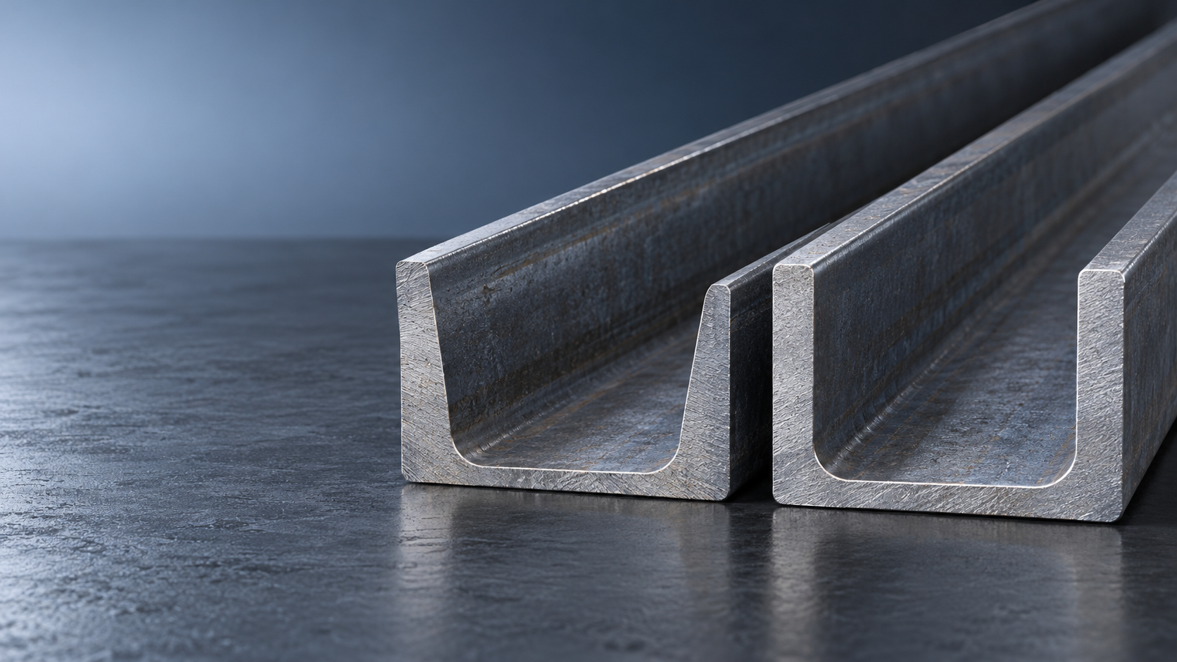
Request UPE when parallel flange faces simplify connections, plate seating and fabrication. Request UPN when an existing design, replacement requirement or verified structural calculation specifies that section. For either choice, confirm the exact dimensions and section properties before accepting a quotation: equal nominal depth does not establish equal strength, stiffness or compatibility.
The distinction becomes especially important when a channel steel supplier proposes one series as an alternative to the other. A substitution affects flange width, thickness distribution, root geometry and connection fit. Acceptance requires a comparison of the supplied section against both the structural calculations and the fabrication drawings.
Start with the connection geometry
UPN channels have tapered inner flange faces, while UPE channels have parallel flange faces. This difference directly affects components attached through, or seated against, the inside of a flange. Both series have rounded internal roots, so neither provides a completely square corner between the web and flange.
A flat bracket seated against a UPE flange has a simpler bearing interface. With UPN, the inclined inner surface needs an appropriate connection detail. Where bolts pass through the flange, a suitable taper washer or another engineered arrangement may be needed to provide proper seating. An ordinary flat washer does not correct an inclined bearing surface.
That advantage matters less when connections pass only through the web. For a channel used as a web-connected secondary member, structural properties, available dimensions and compatibility with adjoining parts may govern the decision. Selecting UPE solely for easier flange bolting provides little benefit if the design contains no flange connections.
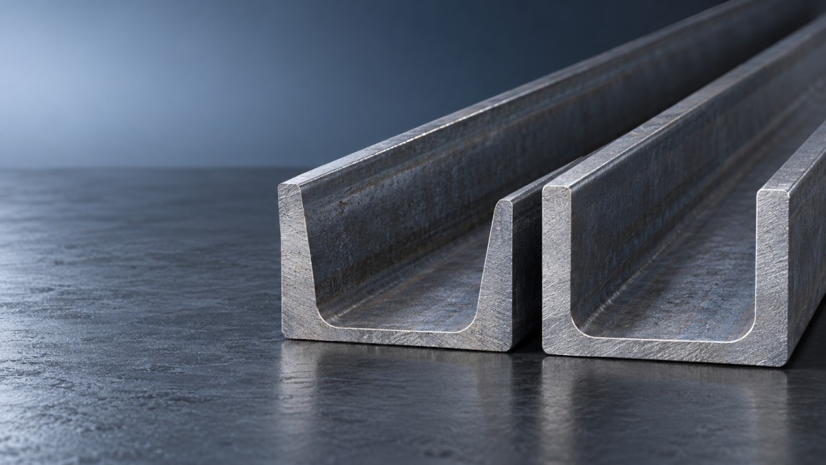
Internal clearance deserves separate attention. A plate that fits between the flange tips can still foul the root radii closer to the web. For an inserted bracket, spacer or nested component, show the required insertion depth and corner relief on the drawing. Nominal clear distance alone does not establish fit.
Compare capacity using the actual section properties
A useful comparison starts with overall depth, flange width, web thickness, flange geometry and mass per unit length. These establish the physical envelope and material distribution. They do not, individually, establish the resistance of the installed member.
For bending about the principal strong axis, compare the relevant section modulus and second moment of area. Section modulus informs bending resistance; second moment of area informs elastic stiffness and deflection. A section can satisfy a stress limit while failing a deflection requirement, particularly where alignment, cladding or equipment clearances restrict movement.
The required elastic or plastic section modulus depends on the design method and cross-section classification. A quoted plastic value is unsuitable as a direct replacement for an elastic value without confirming that the design permits plastic resistance. Similarly, a higher steel grade does not automatically resolve a deflection problem because ordinary structural steel grades have broadly similar elastic stiffness.
For compression members, compare both principal axes and the relevant buckling properties. A channel that appears adequate from its strong-axis properties can still be governed by weak-axis instability or another buckling mode. Effective length, restraint and connection conditions belong in the assessment.
Keep the axis definitions attached to every property comparison. Catalogues and calculation packages do not always use the same axis labels. Confirm the accompanying section diagram, units and orientation before transferring values into a calculation. Confusing the strong and weak axes can produce a plausible-looking result with the wrong engineering meaning.
Open-section twisting can control the choice
A channel is an open, singly symmetric section. Its shear centre lies outside the cross-section, so loading through the web or centroid does not necessarily eliminate torsion. A shelf bracket, edge beam or equipment support can twist even when its bending stress appears acceptable.
Parallel flanges do not remove this behaviour. If torsion or lateral-torsional buckling governs, compare the relevant torsional and warping properties alongside the actual restraint arrangement. The effective solution could involve revised load introduction, additional bracing or a different member arrangement. Changing from UPN to UPE alone is insufficient evidence that the problem has been resolved.
Identify the supplied product beyond its trade name
A quotation reading only “UPE channel” or “UPN channel” leaves too much undefined. The order needs the section designation, dimensional reference, applicable tolerances, steel grade and delivery condition. The dimensional specification defines the profile; the material specification defines properties such as strength and toughness. One does not replace the other.
Confirm whether the offer covers a hot-rolled section. A cold-formed channel or a channel fabricated from welded plates is a different product, even if its external dimensions resemble the requested profile. Corner geometry, thickness distribution, residual stresses and the applicable design treatment can differ.
Where the supplier uses a local designation or claims an equivalent section, obtain a dimensioned drawing and a traceable section-property table. An equivalence statement based only on depth or approximate weight is inadequate for substitution. The comparison must include the dimensions and properties used in the project calculations.
Steel grade also needs its complete designation. Strength alone does not describe toughness requirements, delivery condition or suitability for the intended fabrication. Where impact toughness matters, the required test temperature and quality designation must follow the project specification. Avoid accepting a general description such as “structural mild steel” in place of a defined grade.
Fabrication details that change the preferred series
UPE is often the practical choice for assemblies with repeated flange-mounted plates, bolted attachments or close-fitting brackets. Parallel surfaces reduce the need to accommodate flange slope in each connection. That benefit is strongest where the assembly actually uses those surfaces as bearing or positioning references.
UPN remains a sensible choice for a replacement member where existing brackets, hole positions and adjoining sections were designed around its geometry. Substituting UPE could require redetailing even when its calculated resistance is adequate. Connection compatibility and structural adequacy are separate acceptance conditions.
For welded assemblies, assess access before choosing the section. The flange-to-web root radius restricts how closely a square-edged plate can approach the corner. Fillet weld placement, electrode or torch access, and inspection access all need sufficient space. UPE's parallel flanges do not remove these restrictions.
Weldability follows the material chemistry, thickness, delivery condition and welding procedure. The profile designation does not establish whether preheat is required or which consumable is suitable. Where welding is planned, obtain the relevant material information and confirm the procedure against the actual joint, including restraint and heat input requirements.
Cutting and punching also deserve explicit drawing notes. A hole positioned near the flange root must leave room for tooling, the bolt head or nut, and installation tools. A hole that can be produced successfully can still be inaccessible during assembly.
Tolerances matter most at the interfaces
Nominal dimensions describe the intended profile, while tolerances define the permitted variation. Overall depth, flange width, web thickness, flange squareness, straightness and twist affect different parts of an assembly. A channel accepted under its product tolerances can still be unsuitable for a tightly constrained interface unless that interface has been designed with sufficient clearance.
For channels bolted to a rigid frame, straightness and twist deserve attention across the delivered length. Pulling a distorted member into alignment with bolts can introduce unintended forces and leave uneven contact. A short cut sample does not demonstrate the straightness of the full member.
For paired channels, state the required assembly gap and orientation, then consider dimensional variation in both members. Spacer lengths and connecting plates must accommodate the real geometry. If the channels are intended to act together structurally, their interconnections also need to transfer the forces assumed in the design.
Surface treatment changes the finished interface. Where channels will be galvanized or coated, allow for the specified finish at close-fitting parts and define how holes, threads and contact surfaces are handled. Distortion during processing is especially relevant to slender or asymmetric assemblies; the finished condition should be included in dimensional acceptance.
Make an alternative offer technically reviewable
A supplier can propose a useful alternative when the requested section is unavailable, but the offer needs enough information to evaluate it. Keep the original requirement visible and identify every proposed departure. A revised designation without supporting dimensions merely transfers uncertainty into fabrication.
The technical enquiry should establish the following:
- Section identity: the required UPN or UPE designation, dimensional reference and a drawing where connection geometry is sensitive.
- The complete steel grade and delivery condition, together with any project-specific toughness requirement.
- Supply condition and processing: delivered lengths, cutting tolerances, hole details and surface finish. State whether dimensions apply before or after processing.
- Inspection documentation linked to the supplied material, with traceability maintained through cutting when required.
- For an alternative section, a clear comparison of changed dimensions and relevant structural properties, supported by an identifiable source.
An inspection certificate supports the material assessment, but it does not establish that a substitute section fits an existing connection. Likewise, a dimensional report does not prove the required material properties. Each document should answer the particular acceptance question for which it is requested.
At receipt, reconcile the section markings, material documentation and order designation before fabrication begins. Measurements should target the features that govern fit and performance, including any agreed tolerances beyond the standard supply condition. If cutting removes original markings, the agreed identification method needs to preserve the connection between the pieces and their documentation.
Choose against the governing requirement
For a new frame with frequent flange attachments, UPE is a strong starting point because its parallel flange faces simplify detailing. The final size still follows the calculations, restraint conditions and required clearances.
For a replacement within an established UPN assembly, retaining UPN usually avoids unnecessary connection changes. If a different series is proposed, approve the revised geometry and structural assessment before releasing fabrication drawings.
Where either series fits, compare the exact available sections against the governing limit: deflection, bending resistance, buckling, torsion or connection capacity. The request to the channel steel supplier should then identify one defined section and its acceptance requirements. Any alternative should remain a separately documented proposal until its technical differences have been resolved.
Please give us a message