


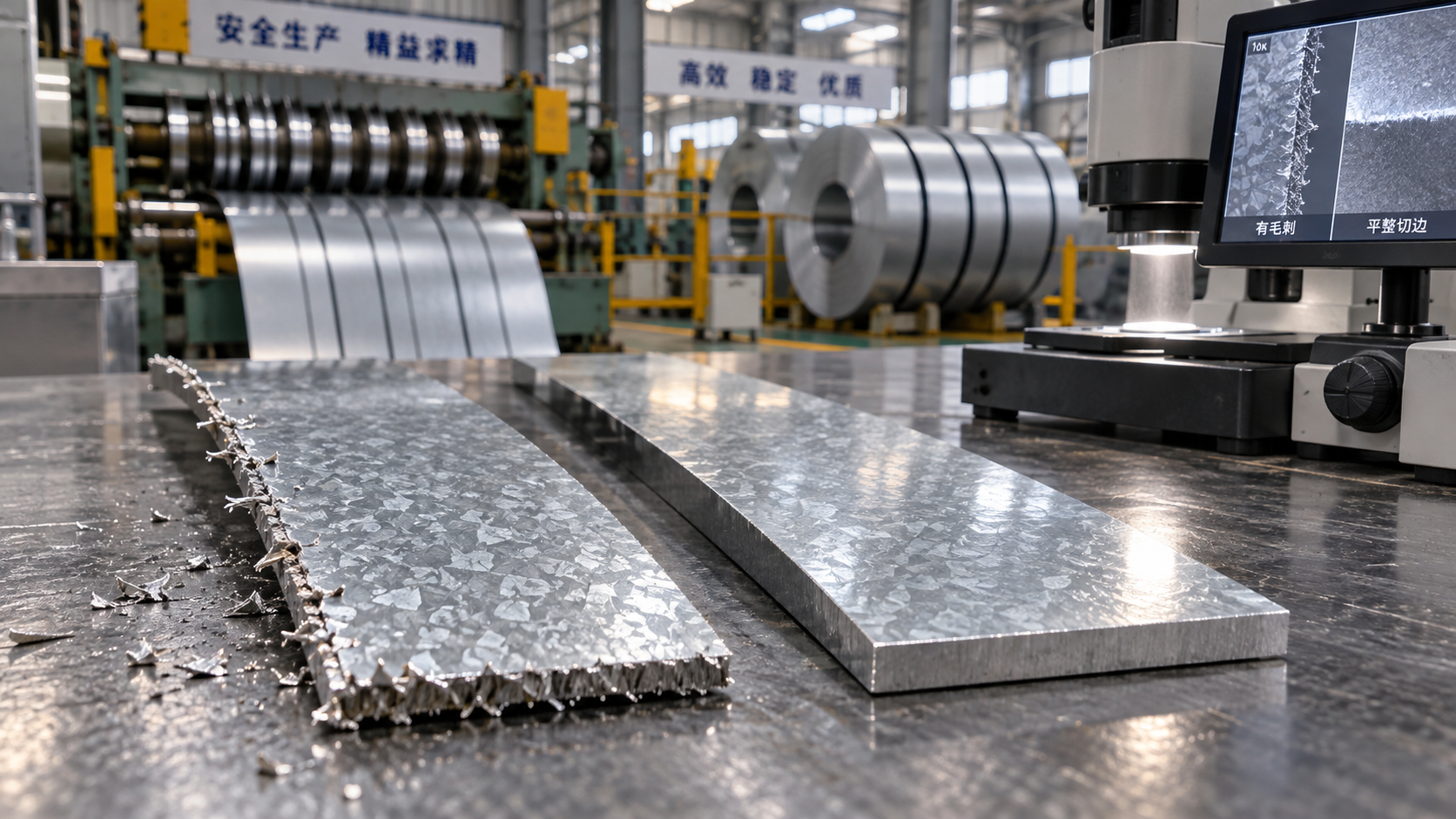
Sharp edge burrs on galvanized sheet metal coils create handling hazards, disrupt downstream forming, and increase rework. Cleaner cuts start with a repeatable, material-specific slitting setup.
For operators, the priorities are correct knife clearance, sound cutting edges, accurate arbor alignment, and stable strip tension. Check these before increasing production speed.
Zinc buildup and unstable strip tracking can spoil an otherwise suitable setup. First identify whether the defect follows one knife position, one strip, or the entire coil.
This guide explains how to diagnose burr patterns, adjust the process systematically, and verify results without unnecessarily damaging the galvanized coating or sacrificing usable material.
What Does the Burr Pattern Tell You?
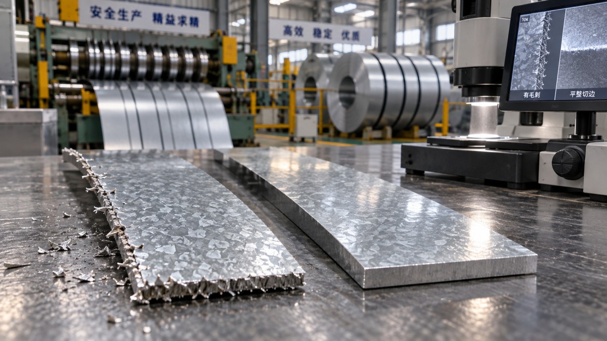
Before changing settings, stop and inspect samples from several slit positions. Label each sample with its strip number, running direction, and upper and lower faces.
A normal slit edge typically contains rollover, a smoother burnished zone, a fracture zone, and some burr. Their proportions depend on material properties and tooling.
A pronounced burr along one edge often points toward localized clearance, blade wear, or alignment trouble. Similar defects across many strips suggest a shared setup problem.
If burr height increases progressively through a run, inspect blade wear and zinc pickup. Also check whether tooling temperature, strip tracking, or tension has changed.
Intermittent burrs deserve a different investigation. Knife damage, arbor runout, loose tooling, and material movement can produce repeating defects that a clearance adjustment alone will not resolve.
Inspect whether the projection is steel, smeared zinc, or loose coating debris. Magnification helps distinguish a fractured steel lip from material adhering to the edge.
Set Knife Clearance from the Actual Material and Tooling
Horizontal knife clearance controls how the material deforms before separation. Excessive clearance commonly increases rollover and tearing; insufficient clearance can cause secondary shearing and accelerated wear.
Start with the slitter or tooling supplier’s recommendation for the actual steel grade, thickness, strength, and knife arrangement. Galvanized coating designation alone cannot determine clearance.
Measure incoming thickness at representative positions using calibrated equipment. Check whether the setup specification refers to coated thickness or substrate thickness, particularly for thinner material.
Confirm how your machine defines clearance. A displayed value, spacer calculation, or percentage may refer to a specific knife relationship; assumptions can introduce substantial setup errors.
For illustration, if an approved procedure specifies clearance equal to 8% of 1.00 mm thickness, the calculated gap is 0.08 mm for that defined relationship.
That calculation is an example, not a recommended operating value. Use the supplier’s convention and verify the physical setup before assessing the resulting slit edge.
Change clearance in small, documented increments within approved limits. Run a short trial after each adjustment, then compare burr height, edge appearance, and strip dimensions.
Adjust vertical overlap separately according to machine guidance. Excessive overlap increases loading and wear, while inadequate engagement can compromise separation; neither reliably corrects unsuitable horizontal clearance.
Check Knife Condition, Spacers, and Arbor Accuracy
A rounded or chipped knife edge can produce burrs even when nominal clearance is correct. Examine cutting edges under suitable lighting and magnification during safe access.
Follow the site’s isolation and lockout procedure before approaching knives, arbors, or strip paths. Never assess sharpness or burr severity by sliding fingers along an edge.
Look for chipped areas, rounded cutting corners, scoring, and adhered zinc. Compare the suspect knife with its service record and the tooling supplier’s regrinding criteria.
After regrinding, confirm knife diameter, thickness, parallelism, and edge condition against the tooling specification. Changes in diameter may require corresponding adjustments to the slitter setup.
Clean knife faces, spacers, and mounting surfaces before assembly. Small particles trapped in a stack can shift local clearance and undermine an otherwise accurate calculation.
Inspect spacers for damage and dimensional variation. Confirm stack order, clamping, and tightening procedures, because an unstable assembly can create inconsistent edges across the coil width.
Check arbor runout, bearing condition, and alignment when defects recur despite sound knives. Measurements should follow machine procedures, using the specified reference surfaces and instruments.
If stripper rings are fitted, verify their condition and specified dimensions. Incorrect support or pressure can distort thin strip, affect tracking, and complicate edge diagnosis.
Control Zinc Pickup Without Damaging the Coating
When slitting galvanized sheet metal coils, zinc can transfer onto contact surfaces. Accumulation changes local contact conditions and may contribute to rough edges, marking, or inconsistent separation.
Inspect knife faces and nearby strip-contact components for deposits. Establish cleaning intervals from observed buildup and quality trends, rather than waiting for visibly defective output.
Use cleaning methods approved for the tooling and coating system. Abrasive scraping or unsuitable chemicals can damage cutting edges, strip protective treatments, or contaminate subsequent operations.
Do not add lubricant automatically. Where lubrication is permitted, confirm compatibility with the coating, customer cleanliness requirements, downstream welding, painting, and the slitter’s operating instructions.
Excess fluid can create handling and housekeeping problems, while incompatible residue may cause downstream rejection. Apply only the approved product through the specified delivery method.
Separate coating scuffing from steel-edge burrs during inspection. Both require attention, but cleaning contact surfaces will not restore a worn knife or correct excessive clearance.
Stabilize Tracking, Tension, and Speed Before Fine Adjustment
Strip movement through the knives must remain consistent. Entry misalignment, unstable loop control, or wandering material can change cutting conditions and make burr measurements difficult to interpret.
Check payoff alignment, guides, bridles, separators, and recoiler behavior. Look for side loading or rubbing that could damage an edge after the cut has formed.
Use the approved tension range for the material thickness, strength, and strip width. Excessive tension can stretch or distort strip; insufficient control can allow unstable movement.
For multiple narrow strands, check whether tension distribution remains acceptable across the recoiler. Uneven buildup or separator contact can create problems confined to individual strips.
Establish the initial edge condition at a controlled trial speed. Increase speed in stages while checking burrs, tracking, coating marks, and the stability of winding.
Reducing speed can help expose vibration or control problems, but it does not repair damaged tooling. Treat speed changes as diagnostic adjustments within the approved operating range.
If edge quality deteriorates only after acceleration, investigate dynamic runout, vibration, tension response, and pickup. Record the speed at which the defect becomes repeatable.
Measure Burrs Consistently and Define What Passes
Visual inspection is useful for screening, but acceptance needs a defined measurement method. Agree on burr limits before production, including sample locations and inspection frequency.
There is no single burr limit suitable for every galvanized application. Requirements depend on thickness, downstream forming, exposed-edge handling, assembly clearances, and the customer’s specification.
Measure burr height relative to the adjacent sheet surface using equipment suited to the required resolution. Optical measurement or properly prepared cross-sections may be appropriate.
Ordinary calipers are generally unsuitable for quantifying very small burr projections. Poor positioning or sample deformation can obscure the defect and produce misleading readings.
Inspect both edges and both faces of representative strips, accounting for the knife arrangement. Check outer slit positions as well as strips near the center.
Sample at startup, after tooling or material changes, and at intervals established by the quality plan. Increase checks when trends indicate deteriorating edge condition.
Record the maximum observed burr under the agreed method, alongside width, camber, and coating condition. A cleaner-looking edge still needs to meet the remaining product requirements.
Use a Repeatable Correction Sequence on the Shop Floor
A disciplined sequence reduces wasted trials and makes successful settings reusable. Keep one approved sample available so operators can compare subsequent output against an established reference.
- Confirm coil identity, steel grade, measured thickness, coating information, and the customer’s edge acceptance requirement.
- Map the defect by strip position, edge, face, and distance along the coil.
- Inspect safely for knife damage, zinc pickup, dirty spacers, loose assemblies, and abnormal contact.
- Verify clearance, overlap, alignment, and runout against the applicable setup procedure.
- Run a controlled trial, changing one relevant variable at a time.
- Measure the result, approve the setup, and monitor quality as speed increases.
If an adjustment produces no meaningful improvement, return to the documented baseline before testing another cause. Multiple simultaneous changes make diagnosis slower and less reliable.
Quarantine affected production according to the site’s quality procedure. Record where the defect began so inspection or rework can target the appropriate coil length.
Avoid using downstream deburring to conceal an unstable slitting process. Additional edge treatment may remove zinc locally and should meet customer requirements for finish and corrosion protection.
Preserve successful settings by material family, thickness range, tooling identification, and machine. Treat previous records as starting references, then verify them against the current coil.
Specify Incoming Material and Processing Requirements Clearly
Consistent incoming material makes setup more predictable. Ask suppliers to confirm grade, thickness tolerances, coating designation, surface treatment, and any agreed restrictions on edge condition.
Jiangsu Zhongersheng Metal Products Co., Ltd. supplies carbon steel, galvanized steel, and stainless steel products, with processing services that include cutting, bending, punching, welding, and surface treatment.
When requesting galvanized coil processing, provide finished strip widths, tolerances, burr criteria, coil dimensions, and downstream use. Confirm that the proposed processing route meets these requirements.
For mixed-material purchasing, specify 1050 Aluminum Bar separately from galvanized coil requirements; aluminum bar specifications and processing conditions cannot establish suitable galvanized steel slitting settings.
Make Cleaner Edges a Controlled Production Result
Reducing burrs on galvanized sheet metal coils starts with identifying the defect pattern, then verifying clearance, tooling condition, alignment, and strip stability in a controlled sequence.
Use measured results to approve each change. A documented setup, consistent inspection method, and timely cleaning or tooling service make edge quality easier to maintain.
The practical goal is a repeatable edge that satisfies handling and downstream requirements while preserving coating condition. Define that standard, verify startup samples, and monitor production.