


News center
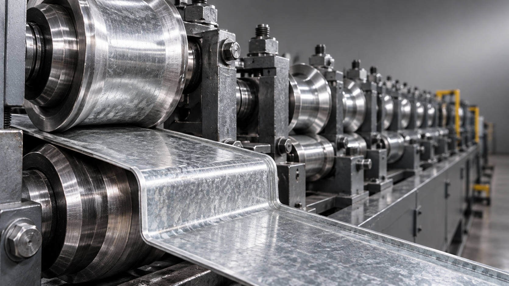
Prevent zinc coating cracks during roll forming by matching the steel grade and coating to the profile, spreading deformation across suitable forming passes, and eliminating unnecessary rubbing or squeezing. Increasing roll pressure rarely solves cracking at an outside bend; it can add surface damage while leaving the underlying strain unchanged. When defects appear, locate the first stand where they develop before changing the setup.
For galvanized rolled coil, distinguish fine coating fissures from loose flakes, longitudinal scratches, and cracks extending into the steel. These conditions require different corrections. Some microscopic fissuring can occur as zinc stretches around a bend, while visible coating separation or substrate fracture calls for investigation before production continues. Acceptance should follow the specified surface, forming, and corrosion requirements rather than appearance alone.
Read the damage before adjusting the rolls
Examine the outside bend, inside bend, and adjacent flat surfaces under good lighting and magnification. Compare the damaged area with an unformed sample from the same coil. A defect already present in the incoming strip needs a different investigation from damage that starts after a particular forming stand.
A surface inspection cannot always establish whether steel is exposed. Where acceptance depends on coating continuity, use the agreed inspection method; a prepared cross-section can help distinguish coating fissures from substrate cracking. Avoid using an improvised tape pull as the sole acceptance test, since preparation and test conditions affect the result.
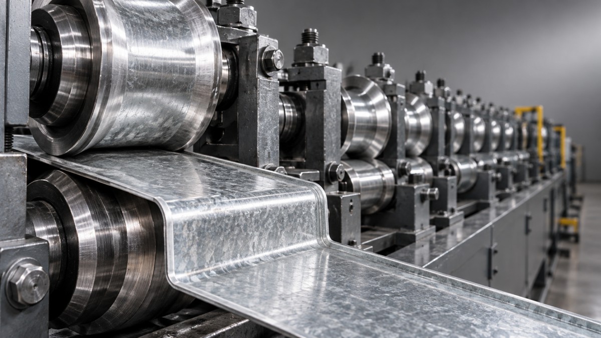
Match the material to the tightest part of the profile
Start with the steel designation, thickness range, coating type, and coating mass recorded for the coil. “Galvanized” describes the protective coating, not the substrate’s forming capability. Two coils with similar appearance and thickness can behave differently because their yield strength, ductility, or coating structure differs.
A higher-strength substrate generally requires more forming force and exhibits greater springback. If the tooling compensates through excessive overbending or repeated correction, local coating strain can increase. Where a profile was developed around a more formable grade, substituting a stronger grade requires a forming review even when nominal thickness remains unchanged.
Coating mass also needs context. A heavier zinc coating provides more zinc for corrosion protection, but its behavior at a tight bend must still be verified. Greater thickness can make coating fracture more pronounced under severe deformation. Reducing coating mass solely to improve appearance risks conflicting with the required service protection; establish a compatible combination of coating, substrate, and geometry.
Conventional hot-dip galvanized steel and galvannealed steel should not be treated as interchangeable. Their coating structures respond differently to deformation, and galvannealed coatings can show powdering under demanding forming conditions. Confirm the supplied coating designation before trying to correct an unexpected surface response through machine settings.
Keep setup records specific to the material and process. Settings from a separate component such as 7075 Aluminum Pipe do not establish suitable bend radii, lubrication, or contact pressures for zinc-coated steel strip.
Bend radius matters, but the strain path matters too
The outside surface stretches as a bend forms, and a smaller inside radius relative to sheet thickness increases that demand. Use the actual formed radius and measured thickness when investigating cracks. A nominal drawing radius or tooling label does not prove that the strip maintains that radius while passing through every stand.
There is no universal minimum radius that guarantees an intact zinc coating across all galvanized grades and profiles. Obtain forming guidance for the specified material, then validate it on the intended tooling. A radius suitable for avoiding steel fracture may still produce a coating appearance that fails the application’s requirements.
Inspect the forming progression, often called the flower pattern, when cracking persists despite an acceptable final radius. A sharp change of angle at one stand concentrates deformation. Spreading that change across additional suitable passes can reduce the severity of each forming step, provided the revised progression controls strip shape and tracking.
Repeated bending and unbending also deserves attention. A corner that is formed, opened, and closed again experiences a more demanding strain history than its final shape suggests. Excessive corrective forming near the end of the mill can damage coating even when the finished dimensions are acceptable.
Longitudinal strain adds another complication. During profile development, edges and central regions travel along different paths. An unsuitable progression can stretch an edge, produce wave, and drive further corrective pressure. When damage occurs alongside edge wave or twist, review strip development and alignment together rather than treating the coating as an isolated problem.
Remove contact damage from the forming process
Set roll clearances using measured incoming thickness, the tooling design, and the intended function of each stand. A universal gap setting is unsuitable because some passes primarily guide the strip while others develop or size the section. Excessive closing force can squeeze the coating, promote pickup, and leave repeated marks.
Zinc pickup often creates a worsening cycle: material transfers to a roll, the raised deposit scores subsequent strip, and additional debris accumulates. Stop and clean the affected tooling with an approved method that preserves its surface and geometry. Abrasive cleaning that changes the roll contour can introduce a new forming problem.
Alignment faults tend to leave patterns. Damage concentrated on one side suggests asymmetric loading, poor strip entry, or misaligned tooling. Regularly repeating marks suggest a rotating contact surface. A scratch continuing through otherwise unformed areas points toward guides or handling equipment as well as the forming stands.
Inspect entry guides, side rolls, straighteners, and exit supports. A guide positioned too tightly can scrape an edge before the first bend develops. Downstream supports can mark a finished surface and make the final forming stand appear responsible. Following the strip path from uncoiler to cut-off helps separate forming damage from handling damage.
Use lubrication to control friction without hiding the cause
Select a lubricant compatible with the galvanized surface, the forming severity, and subsequent operations such as painting or adhesive bonding. An incoming protective oil does not automatically provide enough lubrication for a demanding profile. Conversely, adding excessive lubricant can interfere with traction, leave deposits, and complicate cleaning.
Apply lubricant consistently at the contact zones where sliding occurs. Uneven application can produce alternating clean and damaged lengths, making the problem look like variable coil quality. Inspect delivery nozzles, concentration where relevant, and contamination in recirculating systems. Entrained particles can scratch the coating even when the lubricant itself is suitable.
A controlled reduction in line speed can help reveal vibration, lubricant delivery problems, or heat buildup at heavily loaded contacts. Treat the result as diagnostic evidence. If the defect improves at lower speed, determine which operating condition changed before accepting reduced output as the permanent solution.
Find the first damaging pass with a controlled trial
When the cause remains unclear, preserve the original settings and investigate one variable at a time. Changing pressure, lubrication, alignment, and speed together removes the evidence needed to identify a stable correction.
- Retain reference samples. Label an incoming flat sample and a defective finished section with the coil identification, strip orientation, and location of damage. Record whether the defect remains on the same profile feature or shifts during production.
- Run a short controlled length under the established setup. Stop and isolate the equipment before accessing tooling or inspecting material inside guarded areas.
- Trace the defect upstream. Using safe access arrangements, examine material after successive forming stages to find where damage first appears. If intermediate material cannot be accessed safely, use the machine’s approved trial procedure.
- Make the correction supported by the evidence: remove a pickup deposit, restore alignment, adjust a verified clearance, or revise the deformation sequence. Keep the other settings stable.
- Inspect the resulting surface and profile dimensions together. A cleaner bend that introduces twist, incorrect angles, or unstable tracking has not established a usable setting.
If a previously successful setup begins producing cracks immediately after a coil change, compare material records and measured properties before extensively resetting the mill. If damage develops gradually within one coil, tooling buildup, lubricant delivery, and thermal effects deserve early attention. These patterns narrow the investigation, although neither proves a cause by itself.
Decide whether the result is acceptable
Fine coating fissures do not automatically predict immediate red rust. Zinc can provide sacrificial protection to nearby exposed steel, but that protection has practical limits governed by exposure, damage geometry, and remaining coating. Visible flaking, broad bare areas, and cracks through the substrate require a different assessment from isolated microscopic fissures.
Evaluate the part against its actual use. An exposed architectural surface, a painted component, and a sheltered internal profile can have different surface acceptance requirements. Where painting follows forming, confirm that loose coating and lubricant residues will be removed by the specified preparation process; paint does not restore poor coating adhesion underneath.
Local zinc-rich repair is appropriate only where the specification permits it and the damage is suitable for that repair method. It should not become the routine response to continuous coating loss along every bend. Recurring damage needs a correction to the material, profile geometry, or forming process.
Once a trial produces acceptable coating condition and dimensions, record the coil specification, measured thickness, tooling configuration, lubrication settings, line speed, and reference samples. Revalidate after a material substitution, tooling repair, or significant profile change, since those changes can alter the strain and contact conditions that protected the coating.
Please give us a message