


News center
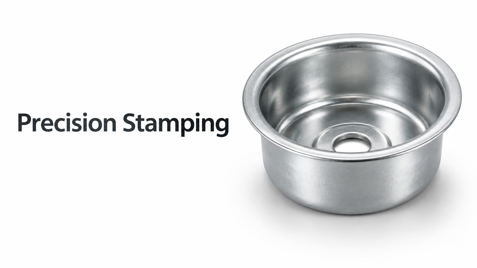
Material Formability and Grade Selection
The base metal of an electro galvanized steel coil dictates its fundamental formability. While the electroplating process provides a smooth, uniform zinc layer that is excellent for painting and corrosion resistance, the underlying steel's microstructure determines how it behaves under complex stress states. When cracks appear during stamping, the first variable to verify is whether the material grade matches the severity of the drawing operation.
Commercial Quality (CQ) steels are designed for simple bending, rolling, or structural applications, not deep drawing. Their yield strength can fluctuate significantly across a single coil, and they lack the necessary ductility for severe deformation. Attempting to stamp a complex, deep-drawn part from CQ electro galvanized steel will almost inevitably result in tearing at the punch radius or the cup wall.
For deep drawing applications, Drawing Quality (DQ) or Deep Drawing Quality (DDQ) grades must be specified. The critical metallurgical parameters for these grades are the strain hardening exponent (n-value) and the plastic strain ratio (r-value). A high n-value ensures that as the steel deforms, it becomes stronger in the stretched area, distributing the strain more evenly and preventing localized necking. A high r-value indicates that the material prefers to deform in width and length rather than thinning out. In deep drawing, thinning is the primary precursor to cracking. If operators consistently experience bottom-of-cup fractures, evaluating the r-value of the incoming electro galvanized steel coil is a necessary diagnostic step to ensure the material possesses adequate resistance to thickness reduction.
Die Geometry and Clearance Optimization
Once material suitability is confirmed, the physical interaction between the steel and the tooling becomes the next critical factor. The clearance between the punch and the die directly controls material thinning, friction, and the overall drawing force.
If the die clearance is too tight, the electro galvanized steel coil is subjected to excessive ironing. This not only increases the drawing force but also generates immense friction, which can tear the zinc coating and cause galling. The damaged zinc particles then act as abrasives, further increasing friction and leading to a fracture. Conversely, if the clearance is too large, the flange area will wrinkle. As these wrinkles are forced through the die gap, they undergo severe reverse bending and flattening, creating localized high-stress zones that initiate cracks in the drawn wall.
For electro galvanized materials, the clearance should typically be set between 1.05 and 1.15 times the material thickness, depending on the specific grade and thickness. Maintaining this precise gap ensures the material flows smoothly without being unnecessarily stretched or compressed.
Equally important are the punch and die radii. A die entry radius that is too small forces the blank to undergo sharp bending and unbending, drastically increasing the tensile stress on the outer surface of the flange. If the punch radius is too small, the material at the bottom corner of the cup will stretch excessively over the sharp edge, leading to severe thinning and eventual tearing. Maintaining polished, appropriately sized radii is non-negotiable for preventing stress concentrations that exceed the steel's forming limits.
Blank Holder Force and Material Flow Management
The blank holder force (BHF) is the primary control mechanism for material flow into the die cavity. Managing this force is often the most complex aspect of stamping electro galvanized steel coils, as the surface friction characteristics differ slightly from bare cold-rolled steel due to the presence of the zinc layer.
An excessively high BHF restricts the flow of the blank into the die. The material cannot feed into the cavity fast enough to compensate for the punch's downward movement, causing the wall of the drawn part to stretch beyond its limits and tear, usually near the punch radius. On the other hand, insufficient BHF allows the flange to wrinkle. These wrinkles, once drawn into the die wall, create severe localized strain and result in cracking.
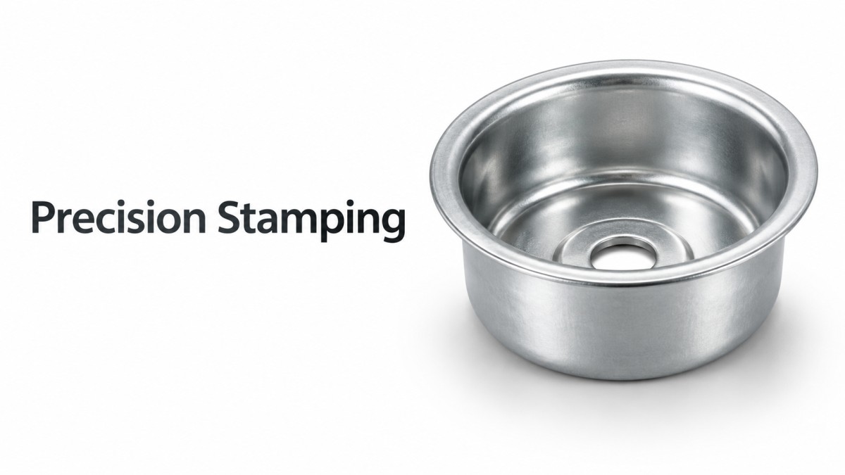
To optimize BHF, operators must recognize that a constant force is rarely ideal for complex geometries. The required force changes as the drawing progresses. Advanced press setups utilize variable blank holder forces or hydraulic cushions that adjust pressure dynamically. In the early stages of the stroke, a lower BHF allows the material to flow freely into the die, reducing the risk of wall tearing. As the stroke completes and the flange area decreases, the BHF is increased to iron out remaining wrinkles and ensure dimensional accuracy.
Furthermore, the lubrication condition directly interacts with the BHF. If the lubricant film breaks down due to excessive pressure or poor application, the friction coefficient spikes. The press control system must be responsive enough to detect these minor load variations, or operators must manually adjust the BHF downward to compensate for increased friction and prevent tearing.
Lubrication and Surface Interaction
The electroplated zinc layer on an electro galvanized steel coil is smooth and relatively soft. While it offers some inherent lubricity, it is highly susceptible to pick-up and galling if the lubrication strategy is flawed. Unlike hot-dip galvanized coatings which have a spangled, rougher surface that can hold lubricants, the smooth electro galvanized surface requires a highly consistent boundary lubrication film.
When the oil film ruptures under high stamping pressures, the bare steel or the zinc layer comes into direct contact with the tool steel. The zinc can adhere to the punch or die surface, creating a rough texture that tears subsequent parts. To prevent this, the selection of the stamping fluid is critical. Lubricants must possess adequate extreme pressure (EP) additives to maintain a protective boundary film under high stress. However, the EP additive concentration must be carefully balanced; overly aggressive additives can react chemically with the zinc layer, complicating subsequent painting or welding processes.
Application uniformity is just as important as the lubricant type. Electro galvanized coils are often oiled at the mill, but this oil can degrade, separate, or wipe off during uncoiling and blanking. Operators must ensure that the blanking line applies a consistent, measurable film of drawing oil to both sides of the blank. Dry spots or areas with insufficient lubrication will experience sudden friction spikes, immediately initiating a tear in the drawn cup.
Edge Quality and Material Aging Effects
Cracks do not always originate in the center of the drawn part; they frequently initiate at the edges of the blank. The method used to cut the blank from the electro galvanized steel coil significantly impacts edge integrity and subsequent formability.
Mechanical shearing creates a fractured edge zone characterized by micro-cracks, rollover, and a work-hardened layer. When this blank is subjected to the biaxial stretching of a deep drawing operation, these microscopic shear defects act as stress concentrators. The cracks propagate rapidly, causing the flange or the drawn wall to split. For deep drawing applications, blanks should ideally be laser-cut, milled, or produced with a clean slitting process that minimizes edge deformation. If mechanical shearing is unavoidable, the sheared edge must be oriented toward a non-critical, non-stretching area of the final part, or the blank must be designed with sufficient trim allowance to remove the work-hardened edge after drawing.
Another hidden cause of cracking is material aging. Electro galvanized steel coils contain interstitial atoms like carbon and nitrogen. Over time, especially if stored in varying temperatures, these atoms migrate to dislocations in the steel's crystal lattice, pinning them in place. This phenomenon, known as strain aging, increases the yield strength and reduces the elongation of the steel. A coil that passed a cupping test upon arrival may fail and crack after several months in the warehouse.
To mitigate this, strict inventory management using the First-In-First-Out (FIFO) principle is mandatory. If aging has already occurred, running the coil through a temper mill for a slight skin pass (typically 0.5% to 1.5% reduction) can unlock the dislocations and restore the material's formability. This process eliminates the yield point elongation that causes stretcher strains and cracks, ensuring the electro galvanized steel coil performs predictably on the press.
Systematic Process Alignment
Preventing cracking when stamping an electro galvanized steel coil is not achieved through a single adjustment but through the precise alignment of material science, tooling geometry, and press dynamics. Operators and engineers must treat the forming process as an interconnected system. By selecting the correct steel grade based on r and n values, optimizing die clearances and radii, dynamically controlling the blank holder force, maintaining robust lubrication, and managing edge quality and material aging, the structural integrity and surface finish of the final metal components can be consistently ensured.
Please give us a message